OFDM
Orthogonal Frequency Division Multiplexing
Technology behind OFDM
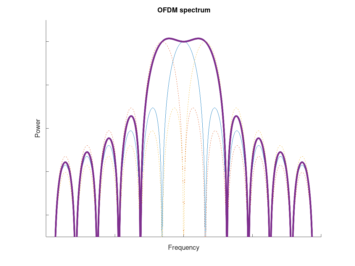
Orthongonal Frquency-Division Multiplexing is a Multi-Carrier Modulation. It is widely used in apllications such as DVB-T, 4G, Wifi, and Powerline Networks.
The Transmitted Data is split up onto many small carriers. Everyone of these carriers is then modulatedwith a Modulation such as QPSK, QAM or BPSK. After allocating all the carriers and adding Sync-Words in front of the Frame the transmission signal is generated throug an IFFT. The IFFT takes all the Channels of one OFDM Symbol and generates a time-signal. Trough calculating the IFFT it is secured that every carrier is Orthogonal to the others. After that the last third of the Samples of the signal are copied to the front of the signal. This is called a Cyclic Prefix. This cyclic Prefix ensures, that the FFT can be used to equalize the transmission signal.
Overview
This page shall describe the frame format generated by the OFDM-Flowgraph. The OFDM-Flowgraph takes in unformated payload data and generates the following additional Information:
- Header Information
- OFDM-Sync words for the Schmidl & Cox synchronisation
- Unused-Carriers for DC and Sideband attenuation requirements
- Pilot-Carriers for receiver synchronisation
Header
Meta information such as length is added to the payload bits by the Protocol Formatter. This additional information is modulated as BPSK in comparison to the QPSK modulated payload.
The Protocol Formatter generates this information from the payload byte stream with the packet_len tag-key (generated by Stream to Tagged Stream). This key marks the beginning of a new frame. The two complex symbol streams (header and payload) are multiplexed into a single stream where the payload follows the header symbols. This is done using the Tagged Stream Mux.
Schmidl & Cox Synchronisation
The 2 pilot symbols are defined as:
-
[0., 0., 0., 0., 0., 0., 0., 1.41421356, 0., -1.41421356, 0., 1.41421356, 0., -1.41421356, 0., -1.41421356, 0., -1.41421356, 0., 1.41421356, 0., -1.41421356, 0., 1.41421356, 0., -1.41421356, 0., -1.41421356, 0., -1.41421356, 0., -1.41421356, 0., 1.41421356, 0., -1.41421356, 0., 1.41421356, 0., 1.41421356, 0., 1.41421356, 0., -1.41421356, 0., 1.41421356, 0., 1.41421356, 0., 1.41421356, 0., -1.41421356, 0., 1.41421356, 0., 1.41421356, 0., 1.41421356, 0., 0., 0., 0., 0., 0.] -
[0, 0, 0, 0, 0, 0, -1, -1, -1, -1, 1, 1, -1, -1, -1, 1, -1, 1, 1, 1, 1, 1, -1, -1, -1, -1, -1, 1, -1, -1, 1, -1, 0, 1, -1, 1, 1, 1, -1, 1, 1, 1, -1, 1, 1, 1, 1, -1, 1, -1, -1, -1, 1, -1, 1, -1, -1, -1, -1, 0, 0, 0, 0, 0]
The inverse Fourier Transformation of those symbols can be seen in the following figures.
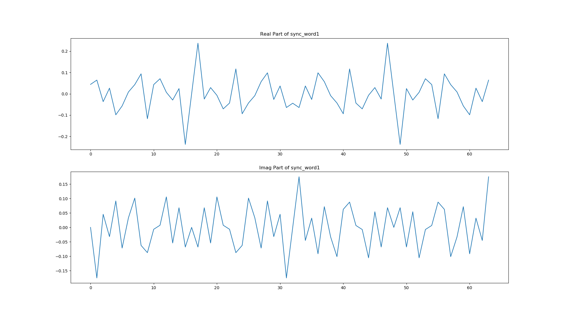
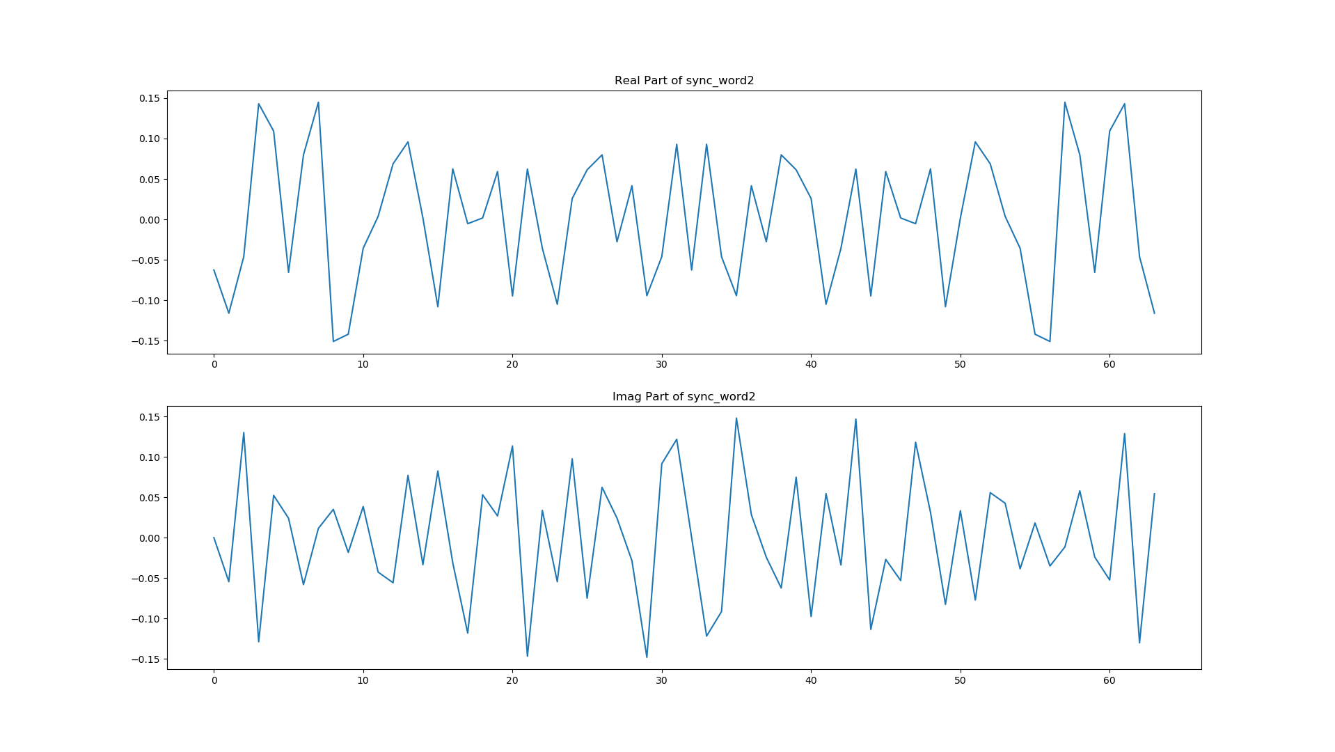
The two figures show the symmetry of the transmitted time signal for the two sync words. The real part of both sync_words is an even function, while the imaginary part is an odd function.
These properties are necessary for the Schmidl & Cox Synchronization to function correctly.
See dspillustrations for more details on the algorithm.
Carrier Allocator
To attenuate the out-of-band emissions the outer carriers are not used and therefore set to 0. This happens in the OFDM Carrier Allocator with the Occupied Carriers option:
(range(-26, -21) + range(-19, -7) + range(-6, 0) + range(1, 7) + range(8, 21) + range(22, 27))Also pilot carriers are assigned to the following carriers:
(-21, -7, 7, 21)Each pilot carrier continuously transmits the corresponding signal:
(1, 1, 1, -1)Carrier Allocation
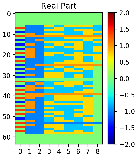
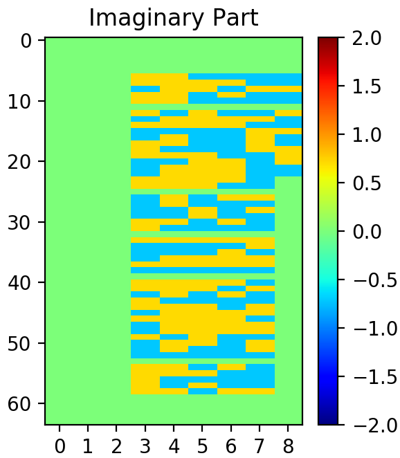
The complex signal is shown in Schmidl & Cox Synchronisation. The first three symbols only use the Real part of the signal (sync_words + header: BPSK). The payload is QPSK modulated so you can see an imaginary amplitude as well.